Flow Diagram Control Circuit Motor Control Circuit Diagram R
Flowchart components Control flow diagram in software engineering: symbols & example Flow control: how solenoid design influences clutch circuits
Flow Chart of Circuit Diagram | Download Scientific Diagram
Flowchart symbols chart flow components template diagram process software diagrams basic component sample program examples shapes flowcharts example conceptdraw simple Flow diagram control example software engineering symbols study video How to read and interpret piping and instrumentation diagrams (p&id
Loop wiring diagram for flow control
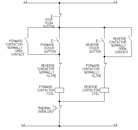
Circuit flow diagramMotor control circuit diagram reverse forward electrical dol schematic star electric starter delta controller flowchart wiring direct line drawing pdf [diagram] three phase motor control circuit diagramAutomatic water level controller circuit project.
What is the difference between power circuit and control give anControl flow diagrams 2: control flow circuit.Flow chart of circuit diagram.

Schematic diagram of flow/pressure valve control: (a) meter-out flow
What is electrical interlocking?Control flow diagram in software engineering: symbols & example Schematic of flow control schemes for mass flow controllers used in theMotor electrical controlsdiagrams.
Instrumentation piping drawing diagrams flow diagram control symbols ids read engineering interpretDcs and plc flow diagram instrumentation tools Diagram block control process system feedback diagrams basics flow figure drawing signals services technologyWiring circuits 3s wires fuse understand.

Electrical interlocking control circuit diagram power diagrams
Flowchart checklistCircuit water level controller automatic simple diagram circuits pump project eleccircuit voltage figure projects Unified arrangementProcess flowchart template – sipoc diagrams.
The basics of process control diagrams – technology transfer servicesCurrent flow in circuit diagram Schematic controllers schemesFlow solenoid control clutch circuits circuit figure influences 6t40 sonnax.

Flowchart schematic diagram for the control circuit of a forward
Bypass flow control circuit – manufacturinget.orgFlow switches: what are they? uses, types, installation Flow control diagramDiagram instrumentation plc system flow dcs control connection basic architecture marshalling cabinet instrument box junction animation controller wiring block systems.
Flowchart sipoc workflow employee charts steps onboardingSql proposed systematic Process flow diagram with control loops for the integrated systemSymbols occurred error.

Flow instrumentation signal practical questions fv instrumentationtools
Flow control graph software cfg engineering example flowchart geeksforgeeks above willControl flow diagram Control flow graph (cfg)How 3 phase motor control circuit works.
Closed loop control circuit diagramSystematic control flow diagram of proposed sql-if approach Flow diagram control circuitSchematic wire.

Circuit diagram
Flowchart organization process flow diagram control flow diagram, pngBasic circuit arrangement of the unified power flow controller Schematic of flow control schemes for mass flow controllers used in theCircuit flow bypass control cylinder manufacturinget position procedure demonstrations slow.
Electrical patentsencyclopedia timingMass controllers semiconductor .


![[DIAGRAM] Three Phase Motor Control Circuit Diagram - MYDIAGRAM.ONLINE](https://i.ytimg.com/vi/wh9qSjhCVHE/maxresdefault.jpg)